General, quoting & support.
Add: Building E, No.58, Nanchang Road, Xixiang , Baoan District Shenzhen City, Guangdong, China
Tel : 0755-27348887
Fax : 0755-27349876
E-mail : svc@pcbastore.com
How to Use a Breadboard
Simon / 2021-04-02
Contents [hide]
What is Breadboard?
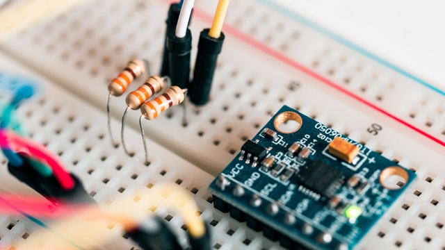
If you're new in using breadboards, you should begin by understanding what it is first. Well, a breadboard refers to the board that electronic engineers and experts use for prototyping. This implies that it is the board used in coming up with experimental models. If you ask electric engineers they will tell you that experimenting is common in the electronics world.
Indeed, experimenting is not a foreign thing in the electronics industry. Designers and engineers invest in the creation of temporary models of electronic circuits before building the final products. In the electronics world, the building and trying of initial versions of electric circuits makes use of electrical components like resistors, battery, LED, and switch.
It is notable to point out that you can use a breadboard for different electronic projects like in automation systems and in weather stations. The physical look of the board is that of a rectangular board that contains small holes in it. It is made of plastic. The many holes on the board serve the function of making it easy for one to insert the electronic components for the purpose of prototyping an electronic circuit. It should not be a complicated thing or process to use breadboards. That is why these tools are ideal for beginner electric projects.

What is Solderless Breadboard?
It's pivotal to understand what solderless breadboard is to get a solid understanding of the circuit making process. From a technical perspective, solderless breadboard refers to a breadboard that doesn't need soldering when making connections. Soldering refers to the process of joining electronic components by melting a metal called solder. Electronic designers and engineers solder electronic components directly, but the most common procedure is that of soldering them to a printed circuit board. A PCB is the board you'll see on your electronic device if you take its cover off. In most cases, engineers use Solderless breadboards to build experimental models of electronic circuits before creating the permanent ones on a PCB. If you have a strong interest in electronics, soldering is something that you need to get acquainted with. Still on soldering, it is important to take note that the connections are permanent and they require special tools for you to get started.
The Breadboard Terminology You Should Know
There is specific terminology that you should know about breadboard. If you look at the modern breadboards, you will notice the numbers, holes, red lines, letters, and blue lines. These are the features that give these tools their distinctive appearance. All these have meanings that you should know.
In reference to numbers, you should be able to identify the horizontal rows. There are numbers starting from 1 through 30 that are printed on the left and the right edges on the half-size breadboards. The full-size breadboards are printed to 60 or 63. The idea here is to have the rows numbered on the breadboards.
In regards to letters, there are letters printed on the breadboards. They are printed on the top and the bottom. The letters are from A to J. You will notice that the letters run horizontally across the board and divide the holes equally in vertical lines.
In is at the horizontal rows that one should have the electronic components connected. For the sake of identifying the rows, this is possible through numbers. A keen look at the board will show you that every row has five holes on each of the sides- the left and the right side. They are separated by a divider. Take note that the 5 holes in the same row are connected electrically. It's important to note that they are on the same side.
The vertical bus has 2 vertical columns that are referred to as power rails. A breadboard has 2 power rails positioned at the ends of each side of the breadboard. The work of the power rail is to join the circuit to a power supply externally. One of the columns serves the purpose of connecting positive voltage with the circuit while the other column serves the purpose of connecting or linking the circuit with the negative.
The central gutter is where a central divider runs vertically and splits the breadboard equally into the left and right sides. It is the central divider that electronically separates the two sides of the breadboard from each other.
Different Types of Breadboard
If you would like to know how to use a breadboard, it's prudent to gain understanding on the types of breadboards that are available today. There are different types of breadboards. The modern types of breadboards are plastic made. They are designed in different sizes, colors, and shapes. The common types in respect to size are the full size, half size, and mini size. It is valuable to highlight that there are sizes that are larger and others that are smaller than the above-mentioned. A mini-sized breadboard is usually ideal for beginner-level projects. So, if you're having beginner projects, you should know how to use a mini breadboard.
Though size is the main aspect that the different types are known by, there are various shapes and colors for you to choose from. If you're particular on the type of color that you would like for your breadboards, there are a variety of them that you can choose from. Of great importance, you should take note that though there are different types of breadboards, all of them follow the same functioning principles and fundamentals.
How to Build a Simple Breadboard Circuit?
An imperative part of learning how to use a breadboard for beginners is being able to build a simple breadboard circuit. There are things that you will need to have for you to build a simple breadboard circuit. They include: a breadboard, wire links, battery, and battery clip. A simple breadboard circuit can light up one light emitting diode (LED).
The first step is to insert the anode part of the LED to the breadboard (rail) and the other part to the main area of the breadboard. After inserting light emitting diode into the board, the next step is to insert the resistor to the breadboard. Using side cutters, take away a 1k resistor. If the resistors are tied together using a tape, do not take away the tape because this can leave the lead of the resistor sticky. The stickiness may end up resting on the breadboard, which will not be good for the process.
Make sure that the leads of the resistor are bent. Since there are two resistor leads, insert one of them into a hole below the cathode side of the LED while the other lead goes into the hole just below the central channel of the breadboard. At this point, one of the resistor leads is connected to the cathode of the light emitting diode.
The third step involves having the wire link inserted into the breadboard. Slot in wire connector to a hole just beneath the resistor lead and into the underneath rail of the breadboard. After doing this, the fourth step is to slot in the battery clip to the breadboard. Take the red wire of the clip, which is the positive one, into the upper rail of the breadboard. Afterwards, insert the black wire of the clip, which is the negative one, into the breadboard's lower rail.
The fifth step is to plug up the battery into the battery clip. You will do this in order to power the circuit and have the LED switched on. Ensure that the connection between the battery clip and the battery is correct. If you the connection is not done in the right way, they two will not clip together as required. The wrong connection may end up damaging the circuit. In order to avoid this, it's good to make sure that the battery connection is in the right way the first time.
Conclusion
A breadboard is a popular tool in the electronics world today. Engineers and product designers use it as the perfect tool for experimental purposes. Both beginner and professional users can benefit greatly from the use of a breadboard. Before the building of the final electric circuits, experimental models are first created, and this is where breadboards come in. There are a myriad of electrical projects that the application of breadboards come to the fore. There are different types of breadboards used today. The main criterion of differentiating these types is the size, though there are also breadboards of various colors and shapes. Once you understand the different types, you can choose the one that suits your needs best.
Something that is of great importance when it comes to using breadboards is getting to understand the various terminologies that describe its structure and functionality. For instance, you should know what the letters, numbers, and lines mean in a breadboard. This is vital for a beginner who does not have an in-depth understanding of the tool. Once you have developed the basic knowledge of a breadboard and how it functions, you can go ahead and build a simple circuit
Previous article:2021 Detail Guide for PCB Conformal Coating


