General, quoting & support.
Add: Building E, No.58, Nanchang Road, Xixiang , Baoan District Shenzhen City, Guangdong, China
Tel : 0755-27348887
Fax : 0755-27349876
E-mail : svc@pcbastore.com

Medical PCB Design Requirements - Reliability, Testing, and Manufacturing Challenges
PCBA Store / 2026-08-19
Contents [hide]
Medical PCB design is not a checklist of premium materials or tighter tolerances. It translates device risks into board-level electrical, mechanical, thermal, manufacturing, and verification controls. The PCB may support essential functions, but compliance and safety belong to the complete medical device, its intended use, software, enclosure, power system, production controls, and documented risk-management process.
Intended Use Defines the Device Risk
The board team needs operating context before selecting stack-up or tests: applied voltages, signal levels, patient or operator proximity, environment, cleaning agents, temperature, humidity, expected life, service access, sterilization exposure if any, and the consequence of a board fault. A diagnostic accessory, laboratory analyzer, wearable, and life-support subsystem can need very different controls.
Risk controls must reach PCB requirements
ISO 14971 provides a framework for medical-device risk management, but practical work is product-specific. If a hazard depends on incorrect sensing, overheating, loss of power, leakage, or communication failure, the responsible team should define board controls and verification evidence that reduce that risk. A generic high-reliability note is not a measurable requirement.
Device standards do not become PCB certificates
IEC 60601-1 addresses basic safety and essential performance for medical electrical equipment at device level. PCB creepage, clearance, insulation, grounding, spacing, and component selection may support that evaluation, but an assembled board alone is not automatically IEC 60601-1 compliant. The manufacturer must map device requirements to the exact circuits and interfaces involved.
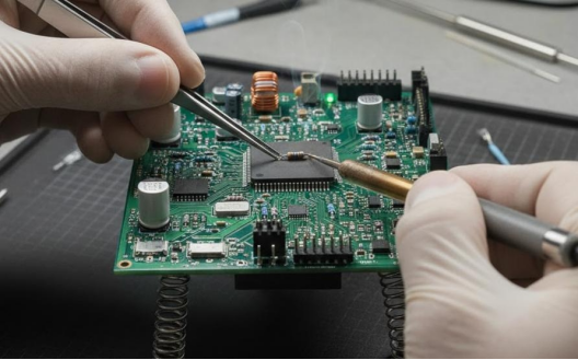
Turn Reliability Goals Into Design Controls
A medical PCB should have a controlled stack-up, material set, copper geometry, finished thickness, surface finish, via structure, and impedance requirements where relevant. Design margins should reflect voltage, current, temperature, transients, contamination, and service life. Derating and thermal analysis are more useful than selecting components only by nominal rating.
Risk area | Board-level control | Typical evidence |
Power and heat | Current margin, protection, thermal paths | Analysis and temperature measurements |
Signal integrity | Reference continuity and interface rules | Rule checks and functional margins |
Insulation | Defined spacing and material assumptions | Layout review and device safety evaluation |
Component integrity | Approved parts and substitution control | BOM approval and traceability |
Assembly | Land patterns, process window, inspection access | DFM review and process records |
Service life | Environment and stress-based validation | Relevant thermal, vibration, or life tests |
Test access should be designed, not added after routing. Provide points for critical rails, programming, communication buses, safety monitors, and diagnostic signals. Keep polarity and reference designators unambiguous, and allow inspection of critical joints. Dense layouts may reduce board area, but hidden risk and impossible rework can increase total device cost.
Build Traceability Into the Manufacturing Package
Control every released input
The manufacturer should receive synchronized Gerber, BOM, centroid, drawing, program, and test revisions. A medical device PCB BOM should identify approved manufacturer part numbers, critical characteristics, allowed alternates, and traceability needs. Special processes such as cleaning, conformal coating, programming, depaneling, and packing need defined instructions and acceptance limits.
A medical PCBA may use SMT, through-hole, mixed technology, fine-pitch packages, or rigid-flex construction. PCBA Store lists these medical PCBA assembly options, with turnkey, consigned, and partial-turnkey sourcing. A medical PCB assembly turnkey service still requires buyer control over critical components, substitutions, shortages, and date-code concerns.
Manufacturing records must support the device file
Lot identity, material status, process settings, inspection results, nonconformance decisions, rework history, programming records, and final test data may be needed to support traceability. The exact record set and retention period belong in the quality agreement or purchase documentation. They should not be inferred after a field issue occurs.
· Define the applicable acceptance class, revision, and customer exceptions.
· Approve alternate components through engineering and quality review.
· Identify critical-to-function features and evidence required for each.
· Separate prototype learning from released production controls and records.

Match Inspection and Testing to Failure Visibility
Visual inspection, AOI, X-ray, ICT, and functional testing address different risks. AOI checks many visible placement and solder features. X-ray supports concealed connections under BGA and QFN packages. ICT can isolate assembly and component faults when access is designed in. Functional testing checks behavior against buyer-supplied procedures, fixtures, limits, and expected outputs.
Structured PCBA testing should trace each test to a requirement or risk control. PCBA Store lists visual, AOI, X-ray, ICT, and functional PCBA testing methods. A medical-device team should define the PCBA testing combination, sampling or coverage, calibration expectations, data format, failure analysis, and disposition rules before quotation.
Board tests do not replace finished-device verification. The assembled medical device may still require electrical safety, electromagnetic compatibility, software, usability, environmental, packaging, cleaning, or other validations based on intended use and market. Likewise, a functional pass at room temperature does not prove reliability across the required service life.
Align Supplier Controls With Current Requirements
In the United States, FDA's Quality Management System Regulation became effective on February 2, 2026 and harmonizes the device current good manufacturing practice framework more closely with ISO 13485:2016. Device manufacturers remain responsible for applicable requirements and supplier controls. A PCB assembler's quality-system statement does not transfer regulatory responsibility or certify the finished device.
A reliable PCBA supplier should demonstrate the actual process needed for the board: revision control, material traceability, equipment controls, inspection capability, calibration, nonconformance handling, rework authorization, change notification, records, and corrective action. The strongest evidence is a documented fit between project risks and supplier controls, not an unrelated certification logo.
Summary: Make Every Requirement Traceable
Reliable medical electronics connect intended use and device risks to board rules, approved materials, manufacturing controls, inspection, functional tests, and retained evidence. Keep device-level compliance distinct from PCB capability, define every critical assumption, and verify the complete product under its real operating conditions.
For a manufacturing review, send PCBA Store the controlled build and test package including quantities, revisions, sourcing rules, inspection scope, records, and acceptance criteria.
FAQ
Does a medical PCB need a specific IPC class?
The required class depends on product requirements and failure consequence. Specify the applicable IPC revision, class, customer exceptions, inspection plan, and records rather than assume every medical board uses one class.
Can a PCB assembler certify the complete medical device?
No. The assembler can provide defined manufacturing and inspection evidence for the PCBA. Device safety, performance, regulatory compliance, and market authorization remain responsibilities of the device manufacturer.
Which tests are most important for medical PCB assemblies?
The correct set follows risk and defect visibility. It may combine visual inspection, AOI, X-ray, ICT, programming verification, and functional testing, plus device-level validation outside the line.
Why is component substitution tightly controlled?
Nominally similar parts can differ in tolerance, temperature grade, lifecycle, dielectric, firmware, noise, traceability, or qualification. Engineering and quality should approve alternates before placement.
What belongs in a medical PCBA quotation package?
Include Gerber files, stack-up and notes, BOM and approved alternates, centroid data, drawings, programming, test procedures and limits, quantities, traceability requirements, special processes, packing, and delivery needs.



