General, quoting & support.
Add: Building E, No.58, Nanchang Road, Xixiang , Baoan District Shenzhen City, Guangdong, China
Tel : 0755-27348887
Fax : 0755-27349876
E-mail : svc@pcbastore.com

PCB Repair or Replacement - How to Decide the Best Solution
PCBA Store / 2026-08-20
Contents [hide]
Repair and replacement are not opposite answers to the same question. Repair restores a defined fault when the damage is understood and the result can be verified; replacement removes uncertainty when the board is unsafe, unavailable for reliable rework, or no longer economical to support. Maintenance teams need a repeatable method that weighs technical recovery, downtime, evidence, and future risk.
Failure Evidence Comes Before Visible Damage
A burned component, lifted pad, or broken conductor may be the final symptom rather than the original cause. Before touching the board, record unit condition, fault codes, operating history, supply voltages, connectors, loads, contamination, and earlier repairs. Then isolate whether the fault belongs to the PCB, a peripheral device, firmware, power source, harness, or environmental event.
Diagnosis defines whether repair is controlled
A repair is credible only when the technician can explain the failure path and verification plan. Replacing a visibly damaged part without checking its driver, load, or protection circuit can recreate the same failure. Diagnostic work should use approved schematics, reference measurements, safe powering methods, and current limits appropriate to the product.
Damage depth changes the answer
Simple surface damage may allow controlled PCB repair, while carbonized laminate, internal-layer damage, widespread corrosion, or repeated overheating can make the remaining structure uncertain. A board that looks clean on top may still have damaged vias, inner conductors, or insulation. The decision must consider what cannot be inspected as carefully as what can.
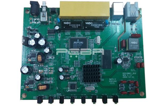
Repair and Replacement Decision Matrix
Decision factor | Repair is stronger when | Replacement is stronger when |
Fault isolation | Cause and affected area are known | Cause or boundary is uncertain |
Safety | Approved repair preserves spacing | Fire, shock, or insulation risk remains |
Board structure | Accessible pad, trace, or component fault | Inner layers or substrate are compromised |
Verification | Required tests can be repeated | No practical way proves recovery |
Downtime | Parts and skill are available | A qualified spare restores service faster |
Lifecycle | Board is obsolete but serviceable | Supported revision improves continuity |
Economics | Total risk-adjusted cost is low | Labor, delay, and recurrence cost more |
The matrix should be weighted by consequence. A low-risk training fixture may justify exploratory work, while a medical, industrial safety, flight, or critical control board can require approved procedures, traceable personnel, and complete requalification. Unit price alone is a poor comparison because a failed repair can add troubleshooting time, secondary damage, missed production, and another service visit.
When a Local Repair Is Technically Reasonable
Accessible conductors and pads can be restored
A controlled pad repair may be appropriate when the surrounding laminate is stable, the electrical connection is known, spacing can be preserved, and the restored feature can be secured and inspected. Each pad repair should match conductor width, current, mechanical load, coating, and operating environment. Improvised pad repair materials can create a new thermal or vibration weakness.
Component replacement may also be reasonable when the failure is isolated, the correct part and process limits are known, and nearby structures remain sound. The technician should protect adjacent components, control preheat and tip or nozzle temperature, limit mechanical force, and inspect the site after cleaning. Rework is a manufacturing process, not simply removal with a hotter tool.
Multilayer damage requires more evidence
Multilayer PCB repair becomes difficult when a via barrel, buried connection, controlled-impedance route, plane, or insulation boundary is affected. Surface continuity does not prove that the internal structure is reliable under heat, vibration, or voltage. If the damaged network cannot be mapped and the board cannot repeat the required electrical and environmental tests, replacement is usually the defensible choice.
· Stop when carbonization, delamination, or corrosion extends beyond the repair boundary.
· Confirm that the product owner permits repair and defines the acceptance test.
· Record the fault, parts, method, operator, inspection, and final test result.
· Separate a temporary recovery action from an approved long-term repair.

When Replacement Reduces Total Risk
Replacement is stronger when damage affects safety isolation, several circuits, connector anchoring, heat-damaged laminate, internal conductors, or a board with repeated unexplained failures. It also becomes attractive when a supported revision corrects known weaknesses, enables available components, or restores warranty and service coverage. The replacement board still needs compatibility checks for firmware, connectors, calibration, and configuration.
Obsolescence can reverse the usual economics. If no qualified replacement exists, a documented repair may keep critical equipment operating while engineering develops a controlled redesign. In that case, the decision should include spare strategy, component authenticity, test fixtures, technical records, and a retirement plan rather than treating each failure as an isolated emergency.
Control Rework and Prove the Outcome
IPC-7711/7721 provides established guidance for electronic-assembly rework, modification, and repair. The selected desoldering methods should match package type, board thermal mass, finish, and damage sensitivity. Different desoldering methods need their own controls; choosing desoldering methods by tool availability alone does not qualify the process.
Verification should repeat tests that can reveal both the original fault and repair-induced damage. That may include visual or microscopic inspection, continuity and isolation checks, powered measurements, functional test, calibration, thermal observation, or a system run under representative load. High-consequence products may require additional validation defined by the responsible engineering organization.
PCBA Store lists AOI, X-ray, ICT, and functional testing among its assembly options. Those capabilities can support a repairability or replacement-build review, but the buyer must define failure evidence, test limits, fixture, sample, and acceptance criteria. An assembler cannot infer device-level safety or service approval from a board image alone.
Summary: Select the Verifiable Recovery Path
Choose repair when the cause and damage boundary are known, the process preserves the required structure, and testing can prove recovery. Choose replacement when hidden damage, safety, repeated failure, unavailable evidence, or total downtime makes repair uncertain. When a team asks can PCB be repaired, the best answer restores function with documented and proportionate risk.
For a replacement-build review, contact PCBA Store with the board files and test plan so missing production inputs can be identified before quotation.
FAQ
Can PCB boards be repaired after a trace is damaged?
Often, yes, when the path is known, surrounding laminate is stable, current and spacing requirements can be preserved, and the finished repair can be secured, inspected, and tested.
When should a burned PCB be replaced?
Replacement is usually preferable when carbonization spreads into laminate, safety spacing is compromised, internal layers may be damaged, the root cause remains unknown, or required verification cannot be completed.
Is a trace repair kit enough for multilayer boards?
Not necessarily. A surface kit cannot prove the condition of buried conductors, vias, planes, impedance, or insulation. Multilayer damage needs structural understanding and a verification plan.
How should repair cost be compared with replacement cost?
Include diagnosis, labor, parts, tooling, validation, downtime, logistics, recurrence probability, warranty impact, and another failure's cost. Technician time versus board price understates risk.
What records should accompany a professional PCB repair?
Record the unit and revision, fault, root cause, affected locations, parts, approved method, operator, inspection results, test limits, final results, and any restrictions on future use.



