General, quoting & support.
Add: Building E, No.58, Nanchang Road, Xixiang , Baoan District Shenzhen City, Guangdong, China
Tel : 0755-27348887
Fax : 0755-27349876
E-mail : svc@pcbastore.com

PCB-to-PCB Soldering vs Board Connectors
PCBA Store / 2026-11-06
Contents [hide]
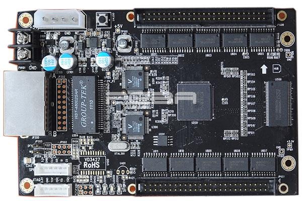
A board connection is also a repair decision. Soldering a small module onto its carrier may make sense until the The board connection is also a repair decision. It is sometimes sensible to solder a tiny module to its board holder but the service plan can require disconnecting it later. This dilemma should be sorted out by an OEM team before making a PCB-to-PCB soldering versus board connection comparison. The good comparison will cover not only soldering procedure but also connection space and the case when one board needs to be removed.
The Separation Requirement
Desoldering is a repair operation in its own right. A soldered module can sometimes be removed, but someone needs the tools, access, and control of the heat. Decide whether the repair plan can accommodate that work. Routine board exchange on site generally calls for a different arrangement.
Unplugging avoids heat at the interconnect, provided the finished product leaves room to do it. Review the connector's retention and permitted mating duty with the service operation in mind. A part chosen for occasional maintenance may be unsuitable for something removed every day.
The repair policy sets the boundary for the comparison. In an industrial instrument, replacing a daughterboard calls for an accessible interface and a spare-board arrangement. Exchanging the complete assembly changes that calculation. Agree the boundary before finalizing the enclosure.
Where Direct Board Soldering Fits
Castellated modules can be soldered directly to a carrier. The plated half-holes at their edges meet pads on the receiving board, avoiding a connector pair at that interface. This can be a useful low-profile arrangement when the module is intended to stay attached during normal use.
Positioning is part of the soldering problem. Work out how the module will be held against the carrier while its joints form, then review the pad geometry and solder volume for that setup. A hand-built sample provides evidence about that sample; production still needs a repeatable assembly method.
Review the module and carrier together for PCB-to-PCB soldering for production. Our assembly services at PCBA Store cover SMT, through-hole, and mixed technology. To agree a route for a direct connection, we need the specific design and its proposed positioning arrangement.
The Module Has a Thermal History
A populated module brings its earlier soldering history with it. Its components and joints may face another heat cycle when it is attached to the carrier. Review the permitted exposure for the module as supplied, including its materials and components. A bare-board process assumption does not answer that question.
Rework Needs Physical Access
Module replacement needs room for the rework tools. Nearby parts may have to be protected while several joints are heated. Include this operation in the cost comparison if the repair plan expects module removal. Saving the connector pair is only one side of that calculation.
What Board Connectors Add
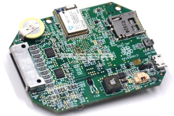
The board positions narrow the choice of PCB connector types. A mezzanine pair suits a different arrangement from a card edge inserted into a socket. Establish orientation, spacing, and mating direction before selecting by signal count. Otherwise, the electrical choice may reserve space the product cannot provide.
Mounting tolerances need to be included in the fit check. Once both boards are fixed to the enclosure, they cannot be aligned freely by hand. Review that stack and the space needed for mating. Having to force the boards together is a reason to investigate, not a normal assembly allowance.
Part numbers make the connector review concrete. For PCB connector types for assembly, include the manufacturer's footprint and process requirements for each selected device. Those are the references needed to assess its SMT or through-hole mounting route; the generic category does not supply them.
Comparing the Two Routes
The permanent joint and the separable interface create different work. Neither earns a universal reliability ranking from its name. Compare the operations your product needs, including how the boards are joined and what a later replacement would involve.
Decision Point | Direct Soldered Connection | Mating Board Connectors |
Routine board replacement | Requires a rework operation | Allows separation if access is designed in |
Space allocation | Can suit a low-profile module | Needs the selected mating geometry and clearance |
Production work | Joint formation and module positioning | Connector placement and final mating |
Mechanical support | Must protect the board joints | Must respect retention and alignment limits |
Cost comparison | Include assembly and possible rework | Include both mating parts and assembly work |
External handling forces need a path through the mounting arrangement. Pushing a cable into the daughterboard is one example. Assess the load against the connector and board limits, then provide support where needed. Small solder joints should not become the default mounting system simply because they already connect the boards electrically.
Electrical requirements can rule out a mechanically convenient choice. Check current ratings for power paths and the relevant interconnect behavior for fast signals. A short joint is not a universal high-speed solution, any more than a large pin count establishes current capacity. Assess the selected implementation.

Production Effort Beyond the Parts List
Assembly cost includes the operations required to make a repeatable connection. A soldered module may need positioning support or a controlled second assembly step. A connector pair needs correct placement and a defined mating operation. Compare those activities on representative assemblies instead of counting only purchased parts.
Joining can hide what was previously easy to inspect. Some module-edge joints remain visible; connections underneath a stacked board may not. Plan the inspection and test sequence around that change in access. Production needs to know which evidence to obtain before closing off the area.
Our process provides inspection and functional testing to customer requirements. Agree the timing of solder pad inspection in assembly while the joining sequence is being reviewed. For an area that will become inaccessible, establish how it will be assessed before that operation proceeds.
A Pilot Build That Tests the Choice
A pilot needs the surrounding mechanical parts to be meaningful. Use the intended mounts and enclosure arrangement where practical, along with the chosen module or connector. Boards that mate easily when held loose may be less forgiving once fixed in position. The pilot is the opportunity to discover that before repeating the arrangement across an order.
Useful questions for that evaluation include:
· Can the assembly team position and join the boards consistently?
· Are the important joints and test points accessible at the right stage?
· Does the mounting arrangement carry the expected mechanical loads?
· Can the intended service operation be performed without damaging adjacent parts?
A Connection That Fits the Product's Life
The connection should support the repair policy as well as the assembly drawing. Keep direct soldering under consideration for permanent modules, and evaluate connectors where separation is useful. Confirm the mechanical arrangement and production sequence in a representative pilot before treating either option as settled.
Bring the proposed module and carrier arrangement to PCBA Store when planning the build; contact us to review the assembly requirements together.
FAQ
Is PCB-to-PCB Soldering Always Cheaper?
Not necessarily. There may be fewer purchased parts, yet positioning and joining the module still take work. Include the inspection route and any expected repair operation when comparing totals. The saving has to be established for the particular design.
What Are Castellated Connections?
These connections use plated half-holes at the module edge, soldered to corresponding carrier pads. They are intentional fabrication features. An arbitrary cut through the edge of an ordinary PCB should not be treated as an equivalent connection.
Are Connectors Better for Replaceable Boards?
Often, yes, because the board can be separated without heating its joints. The finished enclosure still has to allow access and disengagement. Select the connector for the planned service duty rather than assuming all removable interfaces tolerate the same use.
Can a Connector Hold Two Boards Without Other Support?
That requires a mechanical assessment of the actual arrangement. Include handling forces and the parts carried by each board, then compare them with the permitted loads. Where the interconnect cannot carry those loads, provide a suitable mounting path through additional support.
Can an Existing Module Be Reflowed Onto a Carrier?
Check the module's assembly limits and previous thermal exposure before agreeing to another reflow operation. The populated module has components and joints to consider, not just laminate. Successful hand attachment of a sample is not sufficient evidence for that different process.



