General, quoting & support.
Add: Building E, No.58, Nanchang Road, Xixiang , Baoan District Shenzhen City, Guangdong, China
Tel : 0755-27348887
Fax : 0755-27349876
E-mail : svc@pcbastore.com

Fine-Pitch and BGA PCB Assembly for Reliable Boards
PCBA Store / 2026-09-08
Contents [hide]

A compact package can create a surprisingly wide manufacturing risk. On an industrial controller, medical instrument, robot module, or AI edge device, a fine-pitch or BGA part leaves little room for a weak footprint, uneven paste, or an inspection plan added too late. Reliable assembly comes from making those decisions agree before the first board enters the line.
Where Fine-Pitch and BGA Assembly Becomes Difficult
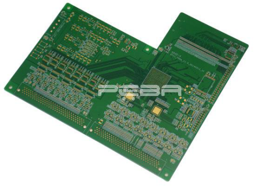
Fine-pitch and BGA devices save board area while shrinking the visual margin for error. A small shift can change pad overlap, and too little solder can leave an open joint hidden below the package. Bridges, head-in-pillow defects, voids, and uneven wetting become more likely when the footprint, stencil, and reflow profile are designed in isolation.
Mixed technology makes the margin tighter still. One board may combine 01005 or 0201 passives, fine-pitch QFPs, BGA processors, connectors, and through-hole parts. Each package reacts differently to paste, heat, placement pressure, and inspection, so a generic SMT recipe is rarely enough.
Three design details that affect yield
· Pad and aperture geometry must support repeatable paste release.
· Thermal balance matters when large copper areas sit beside small pads.
· The inspection and rework plan should be considered before the BGA footprint is frozen.
A clear design-for-assembly review can catch these conflicts early. It also gives the assembly partner a practical basis for discussing panelization, component orientation, stencil design, and test access before the first build.
How Stencil and Placement Control Shape the Solder Joint
Stencil design sets the starting point for solder volume at every joint. PCBA Store uses laser-cut stainless steel stencils for fine-pitch and BGA components, supporting consistent aperture definition. Aperture reduction and the pad-to-aperture relationship still need to be matched to the actual footprint and paste system.
Placement accuracy becomes equally important as pitch decreases. The machine must place each component within the available land pattern while the board remains stable and clean. For dense designs, a controlled component library, verified fiducials, correct centroid data, and a reviewed BOM reduce the chance that an incorrect package or orientation reaches the line.
For teams preparing a new design, the practical PCB assembly capability overview is useful because it connects component size, assembly options, and test methods in one manufacturing conversation. This is especially relevant when a prototype must transition into repeatable industrial or medical production.
Fine-pitch variables worth confirming
Variable | Why it matters | Useful confirmation |
Component pitch | Smaller pitch leaves less room for placement and paste variation. | Confirm the smallest pitch and package family. |
Stencil apertures | Paste volume affects bridging, opens, and joint collapse. | Review aperture strategy for each dense footprint. |
Thermal profile | Uneven heating can produce incomplete reflow or package warpage effects. | Match the profile to the board and component mix. |
Inspection access | Hidden joints cannot be judged by top-side visual inspection alone. | Define AOI, X-ray, and functional coverage before release. |

Why BGA Inspection Needs More Than a Visual Check
A BGA hides its solder joints beneath the package, so visual inspection cannot confirm every connection. PCBA Store lists X-ray inspection for BGA and QFN assemblies, while AOI is used for paste, small components, missing parts, and polarity checks. These methods answer different questions and work best when the inspection plan follows the actual failure modes of the design.
X-ray review is valuable only when the result is interpreted against clear acceptance criteria. Voiding, opens, shorts, misalignment, and unusual solder shapes should lead to a defined decision. In a high-consequence industrial or medical application, that record also helps separate a process issue from a design issue.
A second layer of confidence comes from electrical or functional testing. A board can pass an optical or X-ray check and still fail because of an incorrect value, a programming issue, or an interaction between circuits. Functional coverage should therefore be linked to the customer's test procedure and the intended operating behavior.
Production Inputs That Protect the First Build
The fastest way to lose time on a dense assembly is to begin before the manufacturing data is complete. PCBA Store identifies the BOM, Gerber or other PCB files, and Pick-and-Place data as core inputs for assembly. Clear reference designators, manufacturer part numbers, polarity marks, and approved substitutions reduce questions during setup. The PCB assembly file preparation guide helps keep that handoff tied to the actual build.
Parts condition also affects the outcome. Moisture-sensitive devices, mixed packaging, loose parts, and incomplete kitting can change the line plan. If the assembly includes customer-supplied material, the packing list should make item numbers, part numbers, and quantities easy to reconcile before the feeder setup.
A realistic schedule begins when parts and complete data are ready, not when a purchase order is first issued. PCBA Store describes quick-turn options from 8 to 48 hours after the necessary parts and files are complete. That distinction is useful when planning prototypes or urgent engineering builds because it exposes the real dependency behind a promised turnaround. Teams comparing options can also review the PCBAStore manufacturing capability page for a broader view of the service scope.
A Practical Decision for Dense PCB Projects
Reliable fine-pitch and BGA assembly comes from aligning design, paste deposition, placement, reflow, inspection, and test around the same failure risks. The important questions are not only whether a supplier can place a BGA, but whether the process can show how hidden joints, tiny passives, mixed technologies, and electrical behavior will be controlled.
For a new or revised board, confirm the smallest package, the inspection methods, the data package, and the rework route before releasing production files. A partner that can combine rigid, flex, or rigid-flex assembly with AOI, X-ray, and functional testing can make that review more coherent. The result is a better path from prototype evidence to dependable production.
FAQ
What is fine-pitch SMT assembly?
Fine-pitch SMT assembly places surface-mount components whose leads or pads are closely spaced. It requires accurate placement, controlled paste deposition, and inspection methods suited to small gaps.
Why is X-ray used for BGA soldering?
X-ray allows the team to inspect solder joints hidden under the BGA package. It can reveal patterns associated with opens, shorts, voiding, and uneven solder formation that top-side inspection cannot see.
Can via-in-pad be used with BGA layouts?
Via-in-pad can support dense routing, but the via structure, filling, plating, and surface finish must be designed for the specific board process. It should be reviewed with fabrication and assembly constraints together.
What files are normally needed for a BGA build?
A typical package includes the BOM, Gerber or other PCB files, Pick-and-Place data, and any drawings or photos needed to explain polarity, orientation, and special assembly requirements.
When should BGA rework be planned?
BGA rework should be considered before production when the package is critical, the board is expensive, or access is limited. A defined rework route helps the team respond to an isolated placement or soldering defect without improvising.
Previous article:SMT Assembly Challenges and Engineering Fixes



