General, quoting & support.
Add: Building E, No.58, Nanchang Road, Xixiang , Baoan District Shenzhen City, Guangdong, China
Tel : 0755-27348887
Fax : 0755-27349876
E-mail : svc@pcbastore.com

How to Desolder a Capacitor from a Circuit Board Safely
PCBA Store / 2026-09-09
Contents [hide]
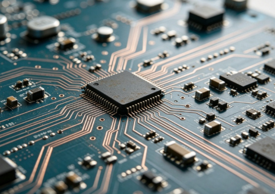
Taking a component off a printed circuit board seems easy at first. However, high heat, leftover electrical charge, cramped spaces, and delicate copper pads can quickly ruin the board. The most secure approach starts with checking the specific component. Next, you must cut off the power supply. Finally, you should focus on choosing among different desoldering methods to find one that fits the component package and the overall board design.
Why Capacitor Removal Needs a Controlled Sequence
These components often store electrical energy long after you unplug a device. This happens mostly in power supplies and high-voltage areas. You must disconnect the main board completely. Allow the circuits some time to discharge safely. Afterward, test the area using a proper multimeter. Do this before your soldering iron or hot air tool ever touches the joint. You should never assume an unlit or quiet board is totally safe to handle.
The next major danger is mechanical damage. Copper connection pads will tear off if you twist the part before the solder fully melts. Too much heat will melt the fiberglass laminate. It can also destroy nearby sensitive parts or break a plated through-hole. Proper rework applies just enough heat to release the connection. It also keeps the heating time as short as possible.
Pre-work checks that prevent avoidable damage
· Write down the exact placement, capacitance value, electrical polarity, and physical direction of the part.
· Unplug the main power completely. Then, confirm the stored voltage has dropped to a harmless state.
· Cover up close plastic pieces, wire connectors, and any items that might melt from high heat.
· Decide exactly where you will put the old component and the new one while you work.
Taking a quick picture helps you remember the correct layout. Drawing a simple diagram works well too. This is especially helpful when many parts look identical. This tiny step saves a lot of trouble later. It allows you to easily check your final repair against the original factory setup.
Choosing the Right Desoldering Method
Finding the perfect approach among various desoldering methods depends on a few factors. These include the component shape, the specific metal alloy, and how much physical room you have. It also matters if the device needs to work perfectly afterward. A standard iron and a vacuum pump perform nicely for standard through-hole pins. Meanwhile, copper braided wick works great for cleaning leftover metal off a flat pad. Hot-air stations assist greatly with flat surface-mount parts. However, this equipment demands careful heat management and protective foil shields.
Putting a tiny drop of new solder on the tip improves thermal transfer. This trick helps melt old or rusty connections much faster. Liquid flux also makes the metal flow smoothly. However, you must clean off any sticky leftovers using safe chemicals. Your main objective is to make the connection let go smoothly. You must never push your hand tools hard through a solid, cold joint.
The PCBA Store assembly and rework capability page is highly useful when your project goes beyond basic manual fixes. Professional tasks like BGA reballing, X-ray inspection, and guided manufacturing support become vital. This is especially true when the circuit is packed tightly, costs a lot of money, or belongs to industrial-grade machinery.
Method comparison
Method | Best suited to | Main caution |
Desoldering pump | Standard pins that have easy physical access. | Never yank the part while the metal remains hard. |
Solder wick | Cleaning leftover metal from flat areas and tiny pins. | Excessive high temperatures or heavy pressing will tear the copper. |
Hot air | Flat chips and components with many tiny legs. | Block heat from nearby items and manage the wind speed. |
Low-melt alloy | Tough connections or spots that absorb too much heat. | Wash away all chemical leftovers and read safety instructions. |
How to Remove the Old Capacitor Without Lifting Pads
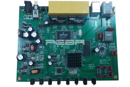
Protecting the delicate copper begins by securing the board firmly. You also need a clean iron tip covered in fresh solder. Apply heat to one single pin or one side of the connection first. Move the part only after you see the metal turn into liquid. If the component features two easy-to-reach pins, switch your heat back and forth between them. This gentle rocking motion lowers the physical stress placed on each individual pad.
Massive ground planes normally soak up a lot of thermal energy. Therefore, the connection might require a thicker iron tip or a bottom preheater. You might also need to adjust your station's temperature carefully. Pushing the dial to maximum heat is not always the best choice. A steady, careful technique keeps the overall melting time brief. It also stops the technician from scratching the board or prying the part against the fiberglass base.
Once the part is gone, check the empty pads using a good magnifying glass. Search for peeled copper, tiny cracks, or broken internal holes. Also watch out for accidental metal bridges and burnt green coating. If a copper circle is completely gone or a wire track is broken, stop your work immediately. You must fix the broken metal pathway first. Do this before you put the new part onto the circuit.
Installing and Checking the Replacement
The fresh component has to match the original storage capacity and maximum voltage exactly. It must also share the same electrical direction, physical size, and heat tolerance limits. A part that merely looks the same is not always a safe substitute. Using the wrong specifications can alter power smoothness. It can also mess up device startup, internal clocks, or overall system balance.
Wash and prep the empty copper spots before you place the new item. Next, melt just enough metal to form a solid, shiny slope. Be careful not to spill liquid metal onto neighboring areas. Hold the part perfectly still and straight while the hot connection hardens. For directional parts, the printed minus or plus symbol must line up perfectly with the board markings. The PCB assembly process reference comes in handy here. It helps a lot when this specific fix turns into a standard, daily factory task.
The PCBA Store PCB assembly service overview explains the larger manufacturing picture. It shows how factories coordinate part loading, melting, and final checking. This broad view is highly important. It matters greatly when the same component breaks repeatedly. Such patterns usually indicate a deep design flaw rather than just one bad piece of hardware.
Post-Rework Tests That Confirm the Repair
Looking closely at your work is the primary step after swapping the part. Double-check the plus and minus directions. Ensure the item sits flat against the surface. Verify that the liquid metal flowed smoothly and the copper remains unbroken. Make sure there are no accidental metal blobs or splashes. Using a microscope proves extremely helpful. This is especially true when working near tiny microchips or bare metal lines.
The testing phase needs to match the danger level of the device. Probe for accidental short circuits between main power lines before you plug it in. Next, turn on the device using a safe, adjustable power supply if possible. Use your meter on the newly fixed area. Compare your readings with the normal expected voltage, current draw, or general system behavior.
A fix is never truly finished merely because the machine lights up. Random glitches, extra heat, weird boot sequences, and strange power usage might hide at first. They often show up only after the device works hard for a while. For expensive industrial gear, running a full operational test builds much stronger trust. Documenting these results is better than just turning it on once. If a whole batch needs the exact same fix, PCBA Store assembly support can guide your next manufacturing audit.
When Bench Rework Should Become a Production Process
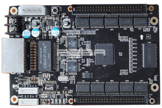
Seeing the exact same component break over and over requires a serious factory investigation. You should not just keep swapping parts endlessly. Write down the exact spot, how it broke, and the specific circuit version. Note the metal quality, the room temperature, and the final fix outcome. Finding common trends can expose hidden heat damage or heavy shaking. It might also show backward installations, bad voltage limits, or poor factory soldering.
Advanced machines like medical tools, factory robots, flying drones, and AI computers need strict repair rules. A guided fix path defends the expensive hardware and keeps maintenance logs clean. If multiple units demand the identical fix, a manufacturing partner can assist. They can turn your desk repair into a standard factory instruction sheet. This sheet will include clear stopping points for visual checks and active testing.
The Practical Takeaway
The most secure answer to how to desolder a capacitor from a circuit board involves a strict routine. First, figure out exactly what the part is. Second, drain the electricity and test the area. Third, pick a gentle removal technique. Next, melt the connection without pushing hard. After that, look closely at the empty copper spots. Finally, put in the right substitute and test the device safely.
Stick to simple hand tools for tiny, familiar fixes. However, you should ask for professional help when dealing with complex, multi-layer designs. Do the same for high-voltage units or extremely crowded layouts. This is also true for constant factory errors. Making a smart choice keeps the delicate copper safe. It also defends the fresh component and the entire machine that relies on your work.
FAQ
Can a capacitor still be dangerous after a board is unplugged?
Absolutely. Certain parts hold onto dangerous electricity long after you pull the plug. Separate the hardware from all power sources completely. Then, check the local area with a reliable digital meter before you start melting anything.
How to Desolder Capacitor Joints Without Lifting Pads
No single trick works perfectly for every situation. A vacuum tool usually handles standard pins very well. Braided copper wire cleans flat spots nicely. Hot air stations work beautifully for specific flat chips, provided you cover nearby sensitive items.
How do I avoid lifting a PCB pad?
Lock your work surface tightly. Keep your iron tip shiny and clean. Apply the correct amount of heat. Use very little physical strength. Never twist or yank the piece until the metal turns completely liquid.
Does the replacement capacitor need the same voltage rating?
The new item must handle the exact power levels of the system. It also needs to share the identical storage size, plus/minus direction, and physical shape. Heat limits and other electrical traits matter just as much. Simply buying a stronger part does not replace reading the full data sheet.
How do I know the repair worked?
Look closely at the fresh metal and copper base first. Probe around for accidentally crossed wires. Next, turn the device on slowly using safe methods. Finally, watch the fixed area perform its normal daily tasks to ensure total success.
Previous article:Fine-Pitch and BGA PCB Assembly for Reliable Boards



