General, quoting & support.
Add: Building E, No.58, Nanchang Road, Xixiang , Baoan District Shenzhen City, Guangdong, China
Tel : 0755-27348887
Fax : 0755-27349876
E-mail : svc@pcbastore.com

LED PCB Assembly for Industrial Lighting Systems
PCBA Store / 2026-09-10
Contents [hide]
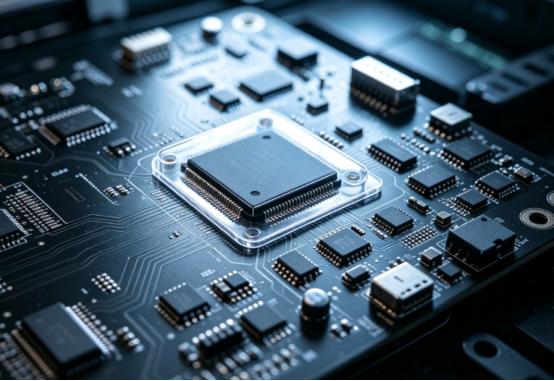
An LED lighting PCB must accomplish more than just providing light. In industrial fixtures, medical devices, machine vision tools, robotics, and inspection setups, the board needs to keep electrical signals stable. It also has to manage heat effectively. Furthermore, it must fit perfectly inside the enclosure. The board must stay reliable across many production batches. A smart LED PCB assembly strategy begins by looking at the operating environment. It does not just focus on the LED package alone.
What the Lighting PCB Must Control
The LED lighting PCB links LEDs with drivers, safety devices, connectors, sensors, and control systems. Its design directly affects current flow. It also impacts heat distribution, optical spacing, and solder strength. A board might work fine during bench testing. However, it could fail in a tightly sealed housing or a continuous-duty fixture.
Industrial lighting usually faces a tougher duty cycle compared to regular consumer decorative lights. A machine-vision ring light might turn on and off very fast. A medical light needs to deliver steady output during long procedures. Meanwhile, a robotic inspection head might deal with constant vibration and repeated motion. These specific working conditions should guide the board stack-up. They should also influence component selection, connector strength, and the overall testing plan.
The four checks behind a stable LED board
l Current regulation needs to align properly with the LED string and the main control setup.
l Thermal paths must function well with the board material. They also need to work with the mounting surface and the outer enclosure.
l LED placement has to remain highly accurate to match the optical and mechanical layout.
l Inspection steps and functional tests should spot polarity mistakes. They must also catch placement errors, bad solder joints, and output problems.
These four checks are closely linked. Yet, they cannot replace one another. Better cooling will not fix a wrong current setting. Also, a flawless optical layout cannot make up for weak solder connections. Making sure each risk stays visible helps keep the entire assembly process much easier to manage.
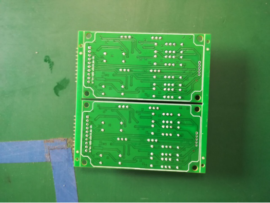
Thermal Design and Board Layout Work Together
Handling heat is frequently the main engineering challenge in LED PCB assembly. LEDs turn electrical power into both light and heat. At the same time, nearby drivers, resistors, and connectors might have their own strict temperature limits. The amount of copper, the use of thermal vias, and the board material all play a role. Mounting pressure and the fixture's cooling route also help determine the final temperature levels.
The board layout needs to protect both electrical and thermal goals. High-current traces require the right width. They also need short return paths. Meanwhile, delicate control signals should stay far away from noisy switching areas whenever possible. LED spacing is crucial too. Even a tiny physical shift can cause noticeable brightness changes. It can also alter the beam pattern in a repeated lighting array.
Reviewing manufacturing capabilities is very helpful at this point. This review links board types, component packages, and placement choices with proper inspection methods. For industrial buyers, the main aim is to connect the LED design with a highly repeatable process. They do not want to treat the board as just a single prototype.
Layout questions for professional lighting
Question | Risk if missed | Production implication |
Where does heat leave the board? | LED output and component lifespan might change as temperatures shift. | Check the copper areas, thermal vias, mounting setup, and enclosure connections. |
How is LED polarity controlled? | A backward component can cause a dark spot. It can also ruin a driver circuit. | Use obvious markings. Perform strict polarity checks during setup and final inspection. |
How are current paths separated? | Electrical noise or a voltage drop can harm brightness and mess up control signals. | Look closely at trace routes, return paths, and connector power ratings. |
How is optical position held? | A slight placement error can lead to obvious uneven lighting. | Manage fiducial marks carefully. Verify placement data and mechanical reference points. |
Assembly Choices That Affect Lighting Consistency
Surface-mount assembly is very popular for LED printed circuit boards. It allows for tight placement and highly repeatable positioning. However, some lighting builds also need through-hole connectors, wire terminals, switches, or physical supports. A mixed assembly approach works well when a connector faces heavy mechanical stress that a simple surface-mount joint cannot handle.
Choosing single-sided or double-sided placement alters the thermal and manufacturing balance. Adding parts to the second side increases functionality. However, it also brings in an extra reflow step or more handling concerns. When a board combines LEDs with bulky capacitors, large inductors, or heavy power devices, the build sequence needs careful review. This prevents shadowing, tombstoning, and poor board support.
PCBA Store offers SMT, through-hole, and mixed assembly services. They also handle single- and double-sided placement. This wide range helps industrial teams manage electrical, optical, and mechanical needs in one clear production talk. At the same time, it lets them pick the most straightforward process. The PCB assembly options for lighting boards provide buyers with a direct spot to check these capabilities.
Testing LED Printed Circuit Boards Before Shipment
LED printed circuit boards require both an assembly check and a real working test. AOI helps spot missing parts, backward components, bad solder, and placement errors. Following that, a functional test confirms the board turns on right. It ensures the board reacts correctly to control signals and gives the required electrical or optical results.
The testing approach must fit the actual application. A simple indicator board might just need a basic power-on and current check. In contrast, a machine-vision light might require checks for even output, smooth dimming, heat levels, or data communication. Medical and industrial buyers should set clear passing rules. These rules must be easy for factory workers to follow every time.
A test report becomes much more helpful when it tells assembly mistakes apart from overall system failures. For instance, an open LED solder joint, a wrong resistor, and a bad driver setting can all look like a broken light. Yet, each issue needs a totally different fix. Having clear test points and baseline measurements speeds up troubleshooting. For a closer look at production, the PCBA Store process and capability overview links testing steps directly to assembly quality.
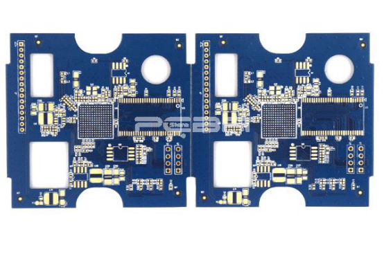
Production Planning for Industrial and Medical Lighting
The most crucial production file for an LED board is a full, clear data package. The BOM needs to list exact manufacturer part numbers and reference marks. Furthermore, Gerber files and Pick-and-Place data must match the final approved version. Clear drawings or photos help explain LED direction, connector placement, and physical alignment.
How parts are packaged affects line setup speed. Reels, cut tape, tubes, trays, loose items, and bulk parts fit different production runs. Still, the assembly kit needs clear labels. A pre-build check finds wrong part counts and packaging mistakes before the line stops running.
PCBA Store provides full turnkey and partial turnkey assembly. Thus, buyers can choose to supply all parts themselves. They can also mix their own parts with sourced ones, or let the provider handle all purchasing. The best choice relies on supply-chain control needs. It also depends on approved-vendor rules and how much buying work the project team wishes to keep.
The Practical Takeaway for LED PCB Projects
A solid LED lighting PCB balances smooth current flow, good heat control, exact optical placement, and tight mechanical fit. It also ensures strong solder joints and passes tough functional tests. The best assembly plan makes these connections clear before the first batch runs. It then uses test results to keep quality high across all future orders.
For industrial, medical, robotic, drone, and AI tools, the next move is to check the board's duty cycle. Teams must verify the heat path, LED layout, driver action, and final testing steps. Once these details match the manufacturing files, the whole assembly process gets simpler to quote, build, check, and refine. A complete one-stop PCB assembly service can then help shift a proven design into steady, reliable production.
FAQ
What is an LED lighting PCB?
An LED lighting PCB is a circuit board. It electrically connects LEDs with power drivers, current-control items, safety parts, connectors, and sometimes sensors or data circuits.
Why is thermal management important for LED boards?
Heat changes LED brightness, driver steadiness, and part lifespan. The board layout, copper design, thermal vias, mounting spot, and outer case must work together. They need to pull heat away from active parts effectively.
Can a PCB for LED lights use both SMT and through-hole parts?
Yes. A mixed assembly can put small LEDs and control parts down using SMT. At the same time, it can use through-hole connectors or strong terminals where physical toughness matters most.
What should an LED board functional test check?
The test should look at power-on action, current levels, and control reactions. It also checks polarity, brightness, lighting evenness, and any data or safety features needed by the final machine.
How can lighting consistency be protected in production?
Use strict placement data and clear polarity guides. Keep component sourcing steady. Set exact inspection rules, and run a reliable functional test using clear baseline measurements.
Previous article:How to Desolder a Capacitor from a Circuit Board Safely



