General, quoting & support.
Add: Building E, No.58, Nanchang Road, Xixiang , Baoan District Shenzhen City, Guangdong, China
Tel : 0755-27348887
Fax : 0755-27349876
E-mail : svc@pcbastore.com

Post-Assembly Testing of Relays, Diodes, Resistors, and Transistors
PCBA Store / 2026-09-11
Contents [hide]
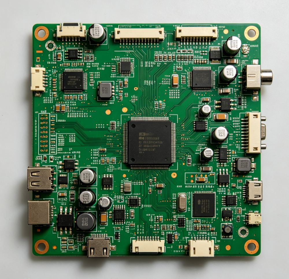
A fully populated board might pass visual inspection. However, it can still fail if a relay does not switch properly. It can also fail if a diode is placed backwards, a resistor has the wrong value, or a transistor is positioned incorrectly. Dependable post-assembly testing blends safe meter checks with a practical functional test. This functional test accurately shows the board's actual performance.
What Each Component Test Is Meant to Prove
A basic component-level check addresses a specific question. It asks if the part is correctly connected and functioning within a predicted electrical range. In contrast, a functional test addresses a wider question. It asks if the completed circuit reacts properly when power, signals, loads, and timing are introduced. Neither method can replace the other.
The distinction matters because in-circuit measurements are affected by parallel paths. A resistor may read low, a diode may be influenced by nearby junctions, and a transistor may appear conductive through a protection path. Test limits should account for the board context.
A sensible test sequence
· Start with visual inspection for orientation, solder, damage, and missing parts.
· Use unpowered resistance or diode checks where they provide clear evidence.
· Apply power through a controlled setup and monitor current.
· Run the functional procedure that exercises the component in its intended role.
How to Test a Relay on a Circuit Board
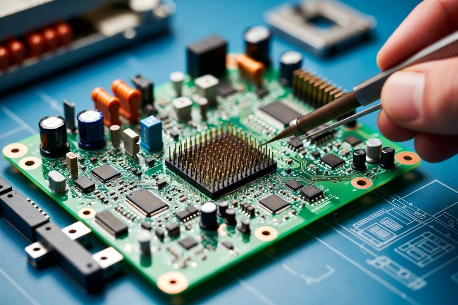
A relay contains at least one coil and a set of contacts, so the test should examine both sides. With power removed, measure the coil resistance and compare it with the expected range. An open coil, a near-short reading, or a value far from the design expectation indicates a problem, but the board circuit may need to be isolated for a meaningful result.
The contact side requires a different check. Identify common, normally open, and normally closed terminals from the schematic. The unenergized relay should show the expected continuity pattern, while the energized relay should change state cleanly.
A repeatable relay test is easier to manage when visual inspection, AOI, X-ray, and functional testing are assigned clear roles. That combination helps separate a solder defect, polarity issue, or incorrect behavior and keeps the corrective action tied to the right stage.
Relay checks at a glance
Check | What it reveals | Important caution |
Coil resistance | Open, shorted, or abnormal coil condition. | Measure against the approved relay specification. |
Contact continuity | Correct normally open/closed behavior. | Use the schematic and isolate parallel paths where needed. |
Energized switching | Whether the relay changes state under its rated drive. | Use the correct coil voltage and current limit. |
Load behavior | Whether the contact carries the intended circuit load. | Test the actual operating condition, not only a dry contact. |
How to Test a Diode on a Circuit Board
A diode is normally tested for one-way conduction. In diode-test mode, the meter should show a forward voltage in the expected direction and an open or much higher reading when the leads are reversed. The exact value depends on the diode technology and the surrounding circuit, so the result should be judged against the part and application.
In-circuit readings can mislead when resistors, coils, protection networks, or other semiconductor junctions create alternate paths. If the reading is ambiguous, lift one lead or isolate the device only when the repair procedure allows it. Avoid applying a test voltage that exceeds the component or board's safe limit.
Polarity is a frequent assembly failure. A correctly soldered diode in the wrong direction can block a supply path, short a protection network, or prevent a control signal from reaching its destination. Markings, footprint orientation, and AOI polarity checks should agree before functional power is applied.
How to Test Resistors and Transistors Together
Resistor testing begins with the marked value, tolerance, and circuit role. With the board unpowered, compare the measured resistance with the expected range while remembering that parallel paths may lower the reading. If the result does not make sense, isolate one side or compare against a known-good board.
A transistor test should confirm both the package orientation and the intended junction behavior. Bipolar transistors have base-emitter and base-collector junctions, while MOSFETs have different gate, drain, source, and body-diode behavior. The correct meter pattern depends on the device type, so the part number and schematic should guide the interpretation.
The PCBA Store one-stop PCB assembly service can be useful for teams that need component placement, soldering, and test planning to stay connected. This is especially helpful when resistor networks, transistor drivers, relays, and diodes interact in an industrial controller or robotics board.
From Component Checks to Functional Testing
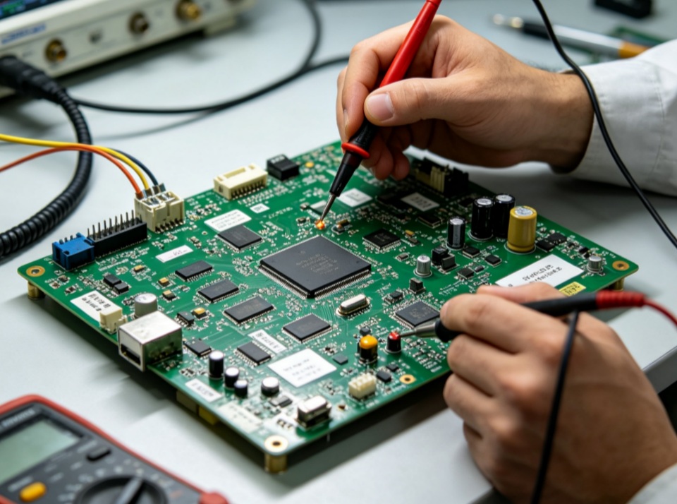
Functional testing should exercise the component in its actual role. A relay test can confirm that a controller command changes the contact state and that the load receives the correct voltage. A diode test can verify protection, rectification, or signal steering.
A functional procedure should define inputs, expected outputs, limits, and timing. It should also identify the equipment required and how the operator records a failure. PCBA Store describes functional testing against customer procedures to check functionality and performance, which turns design intent into a repeatable production test. The PCB assembly testing capability overview gives this test planning a practical manufacturing context.
AOI and X-ray support this process but serve different purposes. AOI identifies visible placement, paste, missing-component, and polarity issues. X-ray supports hidden joints such as BGA and QFN packages. Functional testing confirms electrical behavior that inspection alone cannot prove.
Building a Repeatable Test Record
A test record should identify the board revision, lot reference, equipment, limits, and result. It should separate failed boards from passed boards and support troubleshooting.
Test points and fixtures should support repeatability. A loose probe can create false failures, while an unprotected fixture can damage a connector or short a rail. At higher volumes, a simple jig can reduce operator variation.
The test sequence protects the board. Begin with polarity and resistance checks, limit inrush where possible, and monitor abnormal current before continuing. When a board fails, stop at a defined point and record the symptom rather than repeatedly cycling power. Teams that need assembly and test coordinated can review the PCBA Store production service scope as a reference point.
The Practical Takeaway for Post-Assembly Testing
Testing relays, diodes, resistors, and transistors after assembly is most reliable when each measurement has a clear purpose and the final functional test reflects the circuit's real job. Visual inspection catches visible assembly errors, meters provide targeted evidence, and functional tests show whether the board performs as designed.
For industrial, medical, robotic, drone, and AI equipment, define the test order and acceptance limits before production. Connected inspection and functional procedures give the test process a clearer path from placement to shipment approval.
FAQ
How do I test a relay on a circuit board?
With power removed, check coil resistance and contact continuity against the approved relay specification. Then energize the coil with the correct drive and verify that the contacts switch and carry the intended circuit load.
How do I test a diode on a circuit board?
Use diode-test mode to compare forward and reverse readings. If nearby circuitry creates an ambiguous path, isolate one lead only when the board and repair procedure make that safe.
How to Test Resistors on a Circuit Board
Measure the resistance with power removed and compare it with the marked value and tolerance. Parallel paths may make an in-circuit reading lower, so isolate one side when the result cannot be interpreted confidently.
How are transistors tested after assembly?
Confirm the part number and orientation first, then use a meter pattern appropriate to the device type. Follow with a powered test that checks the transistor in its actual switching or amplification role.
Is AOI enough for post-assembly testing?
No. AOI is valuable for visible placement, solder, missing-component, and polarity checks, but it cannot prove every electrical function. A suitable test plan combines inspection with electrical and functional verification.
Previous article:LED PCB Assembly for Industrial Lighting Systems



