General, quoting & support.
Add: Building E, No.58, Nanchang Road, Xixiang , Baoan District Shenzhen City, Guangdong, China
Tel : 0755-27348887
Fax : 0755-27349876
E-mail : svc@pcbastore.com

How to Scale a PCB Prototype to Mass Production
PCBA Store / 2026-08-28
Contents [hide]
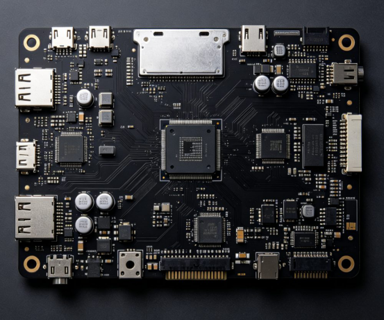
A working prototype proves that a design can function, but it does not prove that thousands of identical units can be produced reliably. The route to mass production must control design data, materials, component supply, assembly, testing, and revisions. Each build should remove a specific production risk before volume is increased.
Why a Working Prototype Is Not Production-Ready
A PCB prototype is primarily an engineering tool. It allows the development team to check electrical performance, mechanical fit, thermal behavior, firmware, connectors, and interfaces before committing to a larger order. Rapid PCB prototyping also makes design changes less costly because only a limited number of boards are affected.
Mass production has a different objective. High-volume PCB fabrication must produce repeatable boards at an agreed-upon cost, yield, quality level, and delivery schedule. A prototype may work after manual rework or the use of a temporary component, but these conditions cannot become part of a stable production process.
The transition therefore depends on measurable release gates:
Manufacturing stage | Main objective | Evidence required before release |
PCB prototype | Confirm design function | Electrical, mechanical, and firmware test results |
Revised prototype | Close identified design issues | Updated files and successful retesting |
Pilot run | Verify the intended production process | Yield, defect, test, and cycle-time records |
Mass production | Maintain repeatable output | Approved files, BOM, process controls, and inspection plan |
Prepare One Controlled Manufacturing Package
Complete documentation prevents avoidable questions during quick-turn PCB fabrication. At minimum, the package should contain Gerber and drill files, a BOM, centroid data, assembly drawings, fabrication notes, and test requirements. Programming files and mechanical drawings should also be included when they affect the finished PCBA.
Revision control is as important as file completeness. A current Gerber package combined with an old BOM can place the wrong component on a valid PCB. A revised footprint without updated centroid data can create placement errors. We recommend assigning the same release identifier to every approved file and removing obsolete files from the production package.
PCB specifications should state the board dimensions, layer count, material, finished thickness, copper weight, surface finish, solder mask, minimum track and spacing, hole sizes, impedance requirements, and panel arrangement. PCBA Store’s online PCB quote system covers common choices such as FR-4, several Tg ranges, 1–16 layers, 1–5 oz finished copper, and multiple surface finishes. Requirements outside the selectable range can be submitted for engineering review.
Good documentation supports manufacturability as well as pricing. IPC’s PCB design training also treats manufacturing and assembly methods, documentation, and manufacturing-file generation as connected design concerns.
Use Rapid PCB Prototyping to Remove Design Risk
The first build should answer defined engineering questions. Checking only whether the PCBA powers on leaves many production risks unresolved. Tests should cover supply rails, current draw, signal behavior, thermal conditions, connectors, controls, communication interfaces, firmware loading, and mechanical fit inside the enclosure.
Each failure should lead to a recorded decision. The team should identify whether the cause lies in the schematic, PCB layout, component specification, assembly process, firmware, or test method. Rework can help confirm a correction, but the reworked unit should not automatically become the production reference. The correction must be incorporated into the released files and confirmed on a clean build.
Quick turn PCB service is most valuable when it shortens this learning cycle. PCBA Store supports low-quantity PCB and PCBA orders, allowing buyers to test a design before committing materials and components to a larger run. Short lead time should not replace engineering review; it should make review and correction faster.

Resolve DFM and DFA Issues Before Scaling
Design for Manufacturability checks whether the bare PCB can be fabricated consistently. The review considers trace and spacing rules, annular rings, drill sizes, copper-to-edge clearance, stack-up, impedance, solder mask openings, board outline, and panel utilization.
Design for Assembly examines how reliably components can be placed, soldered, inspected, and repaired. Typical concerns include unclear polarity, insufficient component spacing, inaccessible test points, unsuitable fiducials, heavy and small components sharing an uncontrolled thermal profile, or connectors positioned where automated assembly becomes difficult.
Standard choices usually improve both speed and cost. A special laminate, unusual board thickness, very small mechanical hole, or uncommon surface finish may be technically justified, but it should be selected intentionally. When a standard option meets the electrical and environmental requirements, it generally offers more stable sourcing and easier repeat production.
Build and Inspect the First PCBA Units
Assembly planning starts with the component package and placement method. PCBA Store supports SMT, through-hole, and mixed-technology assembly, including single- and double-sided placement. Available sourcing models include turnkey, consigned, and partial-turnkey service, allowing buyers to choose whether the manufacturer or customer controls component purchasing.
Inspection should match the risks in the design. AOI can identify missing components, polarity errors, displacement, and visible solder defects. X-ray inspection is more suitable for hidden connections under BGA and QFN packages. ICT checks component values and electrical networks, while functional circuit testing confirms whether the assembled board operates according to the customer’s procedure.
No single inspection method covers every failure mode. A board can look correct under AOI but still fail functional testing because of a wrong component value or programming problem. PCBA Store therefore lists visual inspection, AOI, X-ray, ICT, and functional testing within its PCB assembly services.
Use a Pilot Run to Verify the Production Process
A pilot run should use the intended mass-production files, materials, components, panel design, assembly route, programming method, and test procedure. Its purpose is not to repeat prototype testing. It must show whether the full process can deliver consistent units without exceptional handling.
Useful pilot data include first-pass yield, defect category, rework time, programming time, functional-test duration, material loss, and finished-unit cycle time. For example, if repeated solder defects occur around one package, the team may need to adjust the stencil aperture, pad design, placement settings, or reflow profile before approving mass production.
The pilot also provides an opportunity to approve a golden sample. This reference should include the physical PCBA, its file revision, BOM version, firmware version, inspection record, and functional-test result. A loose sample without this supporting data cannot control later orders.
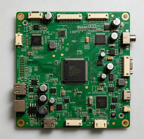
Prepare the BOM for Volume Purchasing
Component availability can delay PCB production even when the bare boards are ready. The BOM should identify the approved manufacturer, exact part number, package, value, quantity, and permitted alternative for each item.
Supply-chain review should flag long lead-time parts, allocation risk, obsolete components, uncertain sources, and high minimum order quantities. Alternatives must be electrically, mechanically, and thermally suitable. A lower-cost substitute should not enter production solely because its description appears similar.
Volume planning should also distinguish setup cost from recurring unit cost. Panel optimization, consolidated component purchasing, automated placement, stable test fixtures, and fewer changeovers can reduce recurring cost. Removing necessary inspection may lower the quotation but increases the risk of rework, field failure, and inconsistent deliveries.
Release High Volume PCB Fabrication with Change Control
Mass production should begin only after the design, BOM, test procedure, and quality criteria are formally approved. Any later change must identify the reason, affected files, implementation date, and first production lot using the revision.
Repeat orders should retain traceable material and process records. Incoming component checks, solder-paste control, placement data, reflow profiles, inspection results, test records, and defect reports help distinguish a design issue from a production variation.
Keeping PCB fabrication, component sourcing, PCBA, and testing within one coordinated workflow can reduce handoff errors. We support this route from prototype quantities through mass manufacturing, but each increase in volume should follow completed validation rather than an assumed result from one successful sample.
Move Your Approved Design into Production
A useful quotation starts with clear files and realistic quantities. Upload your Gerber files through the PCBA Store instant quote platform, or submit the BOM, centroid data, assembly drawings, test requirements, and forecast volumes for a more detailed PCBA review. Our team can help define the practical path from quick-turn samples to repeatable production.
FAQ
How many PCB prototypes are required before mass production?
There is no fixed quantity. The build must provide enough units for electrical testing, mechanical verification, firmware development, reliability checks, and destructive analysis where required. Complex or regulated products normally need more validation units and revisions than a simple commercial board.
What is the difference between a PCB prototype and a pilot run?
A PCB prototype confirms that the design works. A pilot run confirms that the approved design can be fabricated, assembled, inspected, programmed, and tested repeatedly using the intended production process.
Which files are needed for a turnkey PCBA quotation?
A complete package normally includes Gerber and drill files, a BOM with manufacturer part numbers, centroid data, assembly drawings, PCB specifications, target quantity, and test requirements. Firmware and programming instructions should be added when programming is required.
How can PCB production costs be reduced before mass production?
Cost can be controlled through early DFM review, standard materials, efficient panelization, approved component alternatives, consolidated purchasing, automated assembly, and a test process designed for suitable throughput.
Can prototype and mass production orders use the same PCB manufacturer?
Yes, provided the manufacturer supports the required technologies, quantities, quality controls, and component-sourcing model. Using one manufacturing partner can preserve process history and reduce file-transfer and revision-control risks.
Previous article:How to Reduce PCB Manufacturing Costs Without Compromising Quality



