General, quoting & support.
Add: Building E, No.58, Nanchang Road, Xixiang , Baoan District Shenzhen City, Guangdong, China
Tel : 0755-27348887
Fax : 0755-27349876
E-mail : svc@pcbastore.com

Testing Components on Circuit Board: Proven Steps for Reliable Results
PCBA Store / 2026-07-31
Contents [hide]
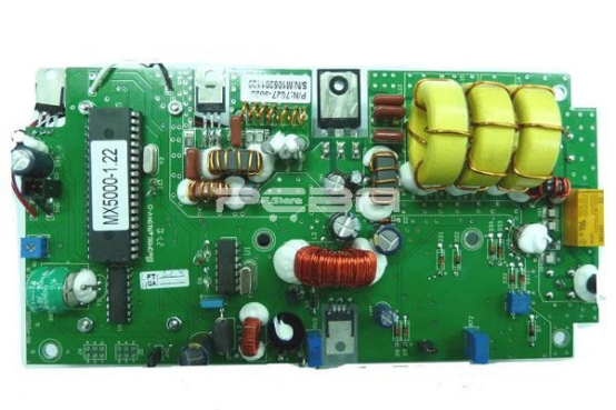
How to Recognize Circuit Board Damage Before Testing?
Common Visual Indicators of Circuit Board Damage
Before performing any diagnostic or electrical measurement on a circuit board it is always wise to visually inspect the board for circuit board damage. Burn marks or discoloration may indicate that a part has overheated or even shorted out. Swollen or leaking capacitors can also cause serious damage to a board, and affect voltage regulation and signal integrity. Additionally, cracked or broken solder joints, or even lifted or warped board edges and corners can cause intermittent faults that may appear to be caused by a faulty component.When checking a circuit board for LED lights for defects, please pay particular attention to signs of heat stress on resistors and on the ICs for voltage regulation, as these are parts that are subjected to high current. The use of magnifying glasses or other visual aids will reveal very fine cracks in the solder joints that are not visible to the naked eye and that could be the root cause of intermittent failures that seem to be caused by a failed component.
How to Prepare the Circuit Board for Accurate Testing
Cleaning and Inspecting the Board Surface
A clean surface ensures accurate contact between test probes and component leads. Use isopropyl alcohol with a soft brush to remove dust, flux residue, and oxidation. This cleaning step is critical when testing circuit board with multimeter, as even small contaminants can affect resistance readings. After cleaning, inspect all traces for continuity breaks or corrosion that might interrupt current flow.
PCBAStore offers rapid PCB prototyping services for quick-turn PCB at high quality and low cost that not only makes PCBs quick but also makes the job right as well as cost-effective. This professional-grade manufacturing quality ensures that new boards undergo fewer manual reworks during testing procedures.
Ensuring Safe Power Disconnection Before Testing
Always disconnect power sources before beginning diagnostics to avoid electric shock and protect sensitive components. Capacitors should be safely discharged using a resistor across their terminals before handling. Label disconnected wires to simplify reassembly after testing. These steps are crucial when learning how to check a circuit board without causing further damage to its components or traces.
How to Evaluate Resistors on a Circuit Board
How to Test a Resistor In-Circuit and Out-of-Circuit
Resistors are among the most straightforward components to test on a PCBA. Set the multimeter to the resistance (Ω) mode and place the probes across both ends of the resistor. Compare the measured value against its color code specification or schematic reference. If readings appear inconsistent due to parallel paths in-circuit, desolder one leg of the resistor for an accurate measurement.
When working on PCB assembly prototype boards from PCBA Store, ensure the reference design documentation provided with each order for precise component values.
Interpreting Resistance Readings Correctly
An infinite resistance reading indicates an open resistor, while zero or near-zero readings suggest a shorted component or parallel path interference. Temperature variations can slightly alter resistance values; therefore, allow components to cool before testing after prolonged operation.
Assessing Diodes for Proper Functionality
Steps to Test a Diode Using a Multimeter’s Diode Mode
To learn how to test a diode on a circuit board, set the multimeter to diode mode. Connect the red probe to the anode and black probe to the cathode; this forward bias should yield a voltage drop between 0.6V–0.7V for silicon diodes. Reverse the probes; there should be no conduction in this direction if the diode is functioning properly.
Diodes play vital roles in circuit board protection, preventing reverse polarity damage and voltage spikes from reaching sensitive ICs.
Identifying Faulty Diodes Through Test Results and Observation
A shorted diode will show low resistance in both directions, while an open diode will display no continuity at all. Physical cracks, burn marks, or melted encapsulation confirm diode failure even before numerical results are reviewed.

How to Test Transistors Effectively on a Circuit Board
Understanding Transistor Configuration Before Measurement
Before learning how to test transistor devices accurately, identify whether it’s an NPN or PNP type using datasheets or body markings. Locate base (B), collector (C), and emitter (E) pins correctly—this is critical when testing transistors on a circuit board since incorrect probing leads to false conclusions about functionality.
PCB Assembly capabilities at PCBAStore include SMT, THT, SMT & THT hybrid, Single or Double Sided Placement, Fine Pitch Components, BGA and more. Understanding these configurations helps people interpret transistor tests within complex multilayer assemblies.
Testing Transistors with a Multimeter in Diode Mode
Checking NPN Transistor Junctions. For NPN transistors, measure base-to-emitter and base-to-collector junctions; both should show forward bias voltage drops around 0.6–0.7V when tested properly.
Checking PNP Transistor Junctions. Reverse probe polarity compared with NPN testing procedures; similar voltage drop values indicate proper function if junctions respond correctly under forward bias conditions.
Detecting Damaged Transistors Through Results. Equal readings in all directions signal internal shorts between terminals—common after overheating events in high-power circuits such as LED drivers. No conduction at all suggests open junctions due to excessive load stress.
Preventive Practices for Maintaining Circuit Board Integrity
Techniques to Minimize Future Component Failures
Maintaining adequate ventilation around high-power parts like transistors reduces heat accumulation that leads to premature failure. Use surge protection devices across power inputs for better circuit board protection against transient voltages. Regular inspection of solder joints followed by reflowing weak connections ensures consistent performance over time.
Functional Circuit Testing (FCT) is a process to verify functionality of a PCBA to assure quality. It can prevent unforeseen decline to fail catastrophically by identifying unseen decline before it is too late.
Benefits of Routine Inspection Before Testing Components
Regular inspections help shorten troubleshooting processes by detecting visible problems at an early stage and creating more reliable conditions for measurements with equipment such as oscilloscopes and digital multimeters. This preventive practice improves the stability of electronic assemblies, from compact consumer devices to industrial control equipment, while helping extend their overall service life.
As a popular PCB manufacturing and assembly company based in China, we have been offering full spec electronic manufacturing solutions for 16 years. Partnering with experienced providers ensures that even prototype boards maintain structural integrity suitable for long-term use under demanding conditions.
Conclusion
Being able to identify circuit board defects by means of visual inspection as well as electrical testing enables people to test faults efficiently and thus avoid replacing parts unnecessarily. By testing for example resistors, diodes or transistors on assembled printed circuit boards by using a structured testing process, people can test these safely and accurately.
FAQs
What tools are needed for testing components on circuit boards?
A digital multimeter capable of measuring resistance, continuity, voltage drop (for diodes), and transistor junction tests are needed in diode mode. For advanced analysis, oscilloscopes help verify signal integrity across active circuits.
How do I safely discharge capacitors before testing?
Use an insulated resistor rated appropriately for voltage levels across capacitor terminals until stored charge dissipates completely—never short them directly with metal tools as this may cause sparks or trace damage.
Can I test components without removing them from the PCB?
Yes—but be cautious of parallel pathways affecting readings when measuring resistors or diodes in-circuit; desolder one terminal if results seem inconsistent compared with expected specifications.
What causes repeated circuit board damage?
Excessive heat buildup due to poor ventilation, overvoltage exposure from unstable power supplies, moisture ingress leading to corrosion, and mechanical stress from improper mounting are common root causes of recurring failures.
Where can I get reliable China PCB assembly services?
PCBA Store provides turnkey PCB assembly services including SMT/THT placement with IPC-A-610F standards compliance and ISO9001-certified quality systems.



